Con este modulo con solo 2 pines del arduino se puede controlar hasta 10 Modulos Relay Serial el cual no solo te limita a solo 10 modulos, puedes habilitar otros 2 pines y asi controlar 10 modulos mas y asi sucesivamente tomanto en cuenta que el Arduino UNO tiene 20 pines podremos controlar hasta 100 relay serial de esta forma.
Modulo de Relay Serial con Arduino UNO puedes comprar tu modulo al siguiente enlace.
O puedes replicar el suyo para probar su libreria el cual pueden descargar en RoboCore como sus modulos funcionan perfectamente, apoyalos comprando a los de RoboCore para que sigan desarollando y mejorando su libreria y/o nuevas funciones que a la fecha funciona perfectamente.
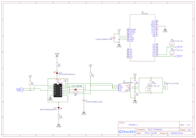
Ya que cada vez es mas comun manejar señales 4-20mA para un Arduino UNO, Leonardo y MEGA 2560 esa Shield es un conversor de 4-20mA a 3.3v asi se puede usar tambien en controladores ESP32 como el raspberry.
No utiliza una resistencia de 250R a la entrada analogica.
Esta Shield maneja con entrada diferencial de 100R a un operacional LM358.
Al
construir esta generador con ATtiny85, nos permite generar una señal
de 4-20 mA activa para poder usar en equipos y/o simular una señal no
requiere tener la fuente de 24v en serie.
Como
funciona este generador, desde el Arduino uno se genera una señal PWM
de 0-255 y con un filtro RC "680R y 100uF" se convierte a una señal
analogica ya que el ATtiny85 no tiene respectivamente una salida
analogica, eso entra al operacional es cual se vuelve a amplificar en
una configuracion de retroalimentacion con una resistencia de R7:250R o
en su defecto usar un R8:1k de presicion pero ajustar a 250R si no
encuentran una resistencia fija.
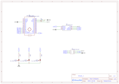
Para
mayor control y presicion se utilizo un encoder ya que no lo permite
hacer el cambio incluye un pulsador el cual permite habilitar un menu en
su programacion.
En simple programacion seria la señal PWM 0-255 su equivalente 0-20mA:
Realizando ingenieria a la inversa se replica este conversor TTL-RS485 que es bidireccional y la habilitacion se realiza por hardware cuando se transmite o recibe datos.
Se utiliza un 74HC14 y componentes pasivos, y el mas485 el que se encarga de este protocolo ya que nos permite manejar hasta un maximo de 1.2km de transmision lo cual se aconseja que al incio y al final en el ultimo equipo se implemente una resistencia de 120R por ello esta shield lo tiene para usar con jumper.
Dependiendo si se usara en un nodo o incio como fin de linea.
Con este modulo nos podemos comunicar TTL-RS485 bidirecionalmente, ya que la habilitacion de transmicion y recepcion lo realiza por hardware.
Una de las ventajas de este protocolo RS485 que podemos extender hasta 1.2km de transmicion el cual se recomienda colocar una resistencia de 120R al inicio y al final de la linea o ultimo equipo, no es necesario que los modulos o equipos en los nodos intermedios tengan esa resistencia.
Modulo bidireccional de TTL-RS232 me permite comunicar equipos con ese protocolo ya sea con PLC o con equipos que manejen ese protocolo ya que es un standar que se mantuvo por mucho tiempo.
El modulo utiliza un chip MAX232 que es el que se encarga de convertir la señal.
Primer programa y puesta en marcha lo primero que se debe realizar es es configuracion del puerto de comunicacion y la velocidad de transferencia, seleccionar la familia del PLC como el modelo, recordar siempre primero compilar el programa para poder cargar al PLC o se generara un error y no les dejara cargar.
Siempre al compilar nos podra marcar si existe errores o no para corregir antes de subir tambien podemos manejar las etiquetas para poder marcar las entradas y/o salidas, es recontra util ya que cuando se hace conplejo un programa y muy extenso nos facilita identificar donde y que sensor el que nos presente algun problema.
Con este quemador AVR podras no solo quemar los bootloader de los Arduinos tambien podras usar en ATtiny85 entre otros, el cual incluye un puerto ICSP para su facil implementacion en los micros de la familia Arduino ya que todas sus placas poseen ese puerto.
// ArduinoISP
// Copyright (c) 2008-2011 Randall Bohn
// If you require a license, see
// http://www.opensource.org/licenses/bsd-license.php
//
// This sketch turns the Arduino into a AVRISP using the following Arduino pins:
//
// Pin 10 is used to reset the target microcontroller.
//
// By default, the hardware SPI pins MISO, MOSI and SCK are used to communicate
// with the target. On all Arduinos, these pins can be found
// on the ICSP/SPI header:
//
//               MISO °. . 5V (!) Avoid this pin on Due, Zero...
//               SCK   . . MOSI
//                     . . GND
//
// On some Arduinos (Uno,...), pins MOSI, MISO and SCK are the same pins as
// digital pin 11, 12 and 13, respectively. That is why many tutorials instruct
// you to hook up the target to these pins. If you find this wiring more
// practical, have a define USE_OLD_STYLE_WIRING. This will work even when not
// using an Uno. (On an Uno this is not needed).
//
// Alternatively you can use any other digital pin by configuring
// software ('BitBanged') SPI and having appropriate defines for PIN_MOSI,
// PIN_MISO and PIN_SCK.
//
// IMPORTANT: When using an Arduino that is not 5V tolerant (Due, Zero, ...) as
// the programmer, make sure to not expose any of the programmer's pins to 5V.
// A simple way to accomplish this is to power the complete system (programmer
// and target) at 3V3.
//
// Put an LED (with resistor) on the following pins:
// 9: Heartbeat   - shows the programmer is running
// 8: Error       - Lights up if something goes wrong (use red if that makes sense)
// 7: Programming - In communication with the slave
//

#include "Arduino.h"
#undef SERIAL


#define PROG_FLICKER true

// Configure SPI clock (in Hz).
// E.g. for an ATtiny @ 128 kHz: the datasheet states that both the high and low
// SPI clock pulse must be > 2 CPU cycles, so take 3 cycles i.e. divide target
// f_cpu by 6:
//     #define SPI_CLOCK            (128000/6)
//
// A clock slow enough for an ATtiny85 @ 1 MHz, is a reasonable default:

#define SPI_CLOCK 		(1000000/6)


// Select hardware or software SPI, depending on SPI clock.
// Currently only for AVR, for other architectures (Due, Zero,...), hardware SPI
// is probably too fast anyway.

#if defined(ARDUINO_ARCH_AVR)

#if SPI_CLOCK > (F_CPU / 128)
#define USE_HARDWARE_SPI
#endif

#endif

// Configure which pins to use:

// The standard pin configuration.
#ifndef ARDUINO_HOODLOADER2

#define RESET     10 // Use pin 10 to reset the target rather than SS
#define LED_HB    9
#define LED_ERR   8
#define LED_PMODE 7

// Uncomment following line to use the old Uno style wiring
// (using pin 11, 12 and 13 instead of the SPI header) on Leonardo, Due...

// #define USE_OLD_STYLE_WIRING

#ifdef USE_OLD_STYLE_WIRING

#define PIN_MOSI	11
#define PIN_MISO	12
#define PIN_SCK		13

#endif

// HOODLOADER2 means running sketches on the ATmega16U2 serial converter chips
// on Uno or Mega boards. We must use pins that are broken out:
#else

#define RESET     	4
#define LED_HB    	7
#define LED_ERR   	6
#define LED_PMODE 	5

#endif

// By default, use hardware SPI pins:
#ifndef PIN_MOSI
#define PIN_MOSI 	MOSI
#endif

#ifndef PIN_MISO
#define PIN_MISO 	MISO
#endif

#ifndef PIN_SCK
#define PIN_SCK 	SCK
#endif

// Force bitbanged SPI if not using the hardware SPI pins:
#if (PIN_MISO != MISO) ||  (PIN_MOSI != MOSI) || (PIN_SCK != SCK)
#undef USE_HARDWARE_SPI
#endif


// Configure the serial port to use.
//
// Prefer the USB virtual serial port (aka. native USB port), if the Arduino has one:
//   - it does not autoreset (except for the magic baud rate of 1200).
//   - it is more reliable because of USB handshaking.
//
// Leonardo and similar have an USB virtual serial port: 'Serial'.
// Due and Zero have an USB virtual serial port: 'SerialUSB'.
//
// On the Due and Zero, 'Serial' can be used too, provided you disable autoreset.
// To use 'Serial': #define SERIAL Serial

#ifdef SERIAL_PORT_USBVIRTUAL
#define SERIAL SERIAL_PORT_USBVIRTUAL
#else
#define SERIAL Serial
#endif


// Configure the baud rate:

#define BAUDRATE	19200
// #define BAUDRATE	115200
// #define BAUDRATE	1000000


#define HWVER 2
#define SWMAJ 1
#define SWMIN 18

// STK Definitions
#define STK_OK      0x10
#define STK_FAILED  0x11
#define STK_UNKNOWN 0x12
#define STK_INSYNC  0x14
#define STK_NOSYNC  0x15
#define CRC_EOP     0x20 //ok it is a space...

void pulse(int pin, int times);

#ifdef USE_HARDWARE_SPI
#include "SPI.h"
#else

#define SPI_MODE0 0x00

class SPISettings {
  public:
    // clock is in Hz
    SPISettings(uint32_t clock, uint8_t bitOrder, uint8_t dataMode) : clock(clock) {
      (void) bitOrder;
      (void) dataMode;
    };

  private:
    uint32_t clock;

    friend class BitBangedSPI;
};

class BitBangedSPI {
  public:
    void begin() {
      digitalWrite(PIN_SCK, LOW);
      digitalWrite(PIN_MOSI, LOW);
      pinMode(PIN_SCK, OUTPUT);
      pinMode(PIN_MOSI, OUTPUT);
      pinMode(PIN_MISO, INPUT);
    }

    void beginTransaction(SPISettings settings) {
      pulseWidth = (500000 + settings.clock - 1) / settings.clock;
      if (pulseWidth == 0)
        pulseWidth = 1;
    }

    void end() {}

    uint8_t transfer (uint8_t b) {
      for (unsigned int i = 0; i < 8; ++i) {
        digitalWrite(PIN_MOSI, (b & 0x80) ? HIGH : LOW);
        digitalWrite(PIN_SCK, HIGH);
        delayMicroseconds(pulseWidth);
        b = (b << 1) | digitalRead(PIN_MISO);
        digitalWrite(PIN_SCK, LOW); // slow pulse
        delayMicroseconds(pulseWidth);
      }
      return b;
    }

  private:
    unsigned long pulseWidth; // in microseconds
};

static BitBangedSPI SPI;

#endif

void setup() {
  SERIAL.begin(BAUDRATE);

  pinMode(LED_PMODE, OUTPUT);
  pulse(LED_PMODE, 2);
  pinMode(LED_ERR, OUTPUT);
  pulse(LED_ERR, 2);
  pinMode(LED_HB, OUTPUT);
  pulse(LED_HB, 2);

}

int error = 0;
int pmode = 0;
// address for reading and writing, set by 'U' command
unsigned int here;
uint8_t buff[256]; // global block storage

#define beget16(addr) (*addr * 256 + *(addr+1) )
typedef struct param {
  uint8_t devicecode;
  uint8_t revision;
  uint8_t progtype;
  uint8_t parmode;
  uint8_t polling;
  uint8_t selftimed;
  uint8_t lockbytes;
  uint8_t fusebytes;
  uint8_t flashpoll;
  uint16_t eeprompoll;
  uint16_t pagesize;
  uint16_t eepromsize;
  uint32_t flashsize;
}
parameter;

parameter param;

// this provides a heartbeat on pin 9, so you can tell the software is running.
uint8_t hbval = 128;
int8_t hbdelta = 8;
void heartbeat() {
  static unsigned long last_time = 0;
  unsigned long now = millis();
  if ((now - last_time) < 40)
    return;
  last_time = now;
  if (hbval > 192) hbdelta = -hbdelta;
  if (hbval < 32) hbdelta = -hbdelta;
  hbval += hbdelta;
  analogWrite(LED_HB, hbval);
}

static bool rst_active_high;

void reset_target(bool reset) {
  digitalWrite(RESET, ((reset && rst_active_high) || (!reset && !rst_active_high)) ? HIGH : LOW);
}

void loop(void) {
  // is pmode active?
  if (pmode) {
    digitalWrite(LED_PMODE, HIGH);
  } else {
    digitalWrite(LED_PMODE, LOW);
  }
  // is there an error?
  if (error) {
    digitalWrite(LED_ERR, HIGH);
  } else {
    digitalWrite(LED_ERR, LOW);
  }

  // light the heartbeat LED
  heartbeat();
  if (SERIAL.available()) {
    avrisp();
  }
}

uint8_t getch() {
  while (!SERIAL.available());
  return SERIAL.read();
}
void fill(int n) {
  for (int x = 0; x < n; x++) {
    buff[x] = getch();
  }
}

#define PTIME 30
void pulse(int pin, int times) {
  do {
    digitalWrite(pin, HIGH);
    delay(PTIME);
    digitalWrite(pin, LOW);
    delay(PTIME);
  } while (times--);
}

void prog_lamp(int state) {
  if (PROG_FLICKER) {
    digitalWrite(LED_PMODE, state);
  }
}

uint8_t spi_transaction(uint8_t a, uint8_t b, uint8_t c, uint8_t d) {
  SPI.transfer(a);
  SPI.transfer(b);
  SPI.transfer(c);
  return SPI.transfer(d);
}

void empty_reply() {
  if (CRC_EOP == getch()) {
    SERIAL.print((char)STK_INSYNC);
    SERIAL.print((char)STK_OK);
  } else {
    error++;
    SERIAL.print((char)STK_NOSYNC);
  }
}

void breply(uint8_t b) {
  if (CRC_EOP == getch()) {
    SERIAL.print((char)STK_INSYNC);
    SERIAL.print((char)b);
    SERIAL.print((char)STK_OK);
  } else {
    error++;
    SERIAL.print((char)STK_NOSYNC);
  }
}

void get_version(uint8_t c) {
  switch (c) {
    case 0x80:
      breply(HWVER);
      break;
    case 0x81:
      breply(SWMAJ);
      break;
    case 0x82:
      breply(SWMIN);
      break;
    case 0x93:
      breply('S'); // serial programmer
      break;
    default:
      breply(0);
  }
}

void set_parameters() {
  // call this after reading parameter packet into buff[]
  param.devicecode = buff[0];
  param.revision   = buff[1];
  param.progtype   = buff[2];
  param.parmode    = buff[3];
  param.polling    = buff[4];
  param.selftimed  = buff[5];
  param.lockbytes  = buff[6];
  param.fusebytes  = buff[7];
  param.flashpoll  = buff[8];
  // ignore buff[9] (= buff[8])
  // following are 16 bits (big endian)
  param.eeprompoll = beget16(&buff[10]);
  param.pagesize   = beget16(&buff[12]);
  param.eepromsize = beget16(&buff[14]);

  // 32 bits flashsize (big endian)
  param.flashsize = buff[16] * 0x01000000
                    + buff[17] * 0x00010000
                    + buff[18] * 0x00000100
                    + buff[19];

  // AVR devices have active low reset, AT89Sx are active high
  rst_active_high = (param.devicecode >= 0xe0);
}

void start_pmode() {

  // Reset target before driving PIN_SCK or PIN_MOSI

  // SPI.begin() will configure SS as output, so SPI master mode is selected.
  // We have defined RESET as pin 10, which for many Arduinos is not the SS pin.
  // So we have to configure RESET as output here,
  // (reset_target() first sets the correct level)
  reset_target(true);
  pinMode(RESET, OUTPUT);
  SPI.begin();
  SPI.beginTransaction(SPISettings(SPI_CLOCK, MSBFIRST, SPI_MODE0));

  // See AVR datasheets, chapter "SERIAL_PRG Programming Algorithm":

  // Pulse RESET after PIN_SCK is low:
  digitalWrite(PIN_SCK, LOW);
  delay(20); // discharge PIN_SCK, value arbitrarily chosen
  reset_target(false);
  // Pulse must be minimum 2 target CPU clock cycles so 100 usec is ok for CPU
  // speeds above 20 KHz
  delayMicroseconds(100);
  reset_target(true);

  // Send the enable programming command:
  delay(50); // datasheet: must be > 20 msec
  spi_transaction(0xAC, 0x53, 0x00, 0x00);
  pmode = 1;
}

void end_pmode() {
  SPI.end();
  // We're about to take the target out of reset so configure SPI pins as input
  pinMode(PIN_MOSI, INPUT);
  pinMode(PIN_SCK, INPUT);
  reset_target(false);
  pinMode(RESET, INPUT);
  pmode = 0;
}

void universal() {
  uint8_t ch;

  fill(4);
  ch = spi_transaction(buff[0], buff[1], buff[2], buff[3]);
  breply(ch);
}

void flash(uint8_t hilo, unsigned int addr, uint8_t data) {
  spi_transaction(0x40 + 8 * hilo,
                  addr >> 8 & 0xFF,
                  addr & 0xFF,
                  data);
}
void commit(unsigned int addr) {
  if (PROG_FLICKER) {
    prog_lamp(LOW);
  }
  spi_transaction(0x4C, (addr >> 8) & 0xFF, addr & 0xFF, 0);
  if (PROG_FLICKER) {
    delay(PTIME);
    prog_lamp(HIGH);
  }
}

unsigned int current_page() {
  if (param.pagesize == 32) {
    return here & 0xFFFFFFF0;
  }
  if (param.pagesize == 64) {
    return here & 0xFFFFFFE0;
  }
  if (param.pagesize == 128) {
    return here & 0xFFFFFFC0;
  }
  if (param.pagesize == 256) {
    return here & 0xFFFFFF80;
  }
  return here;
}


void write_flash(int length) {
  fill(length);
  if (CRC_EOP == getch()) {
    SERIAL.print((char) STK_INSYNC);
    SERIAL.print((char) write_flash_pages(length));
  } else {
    error++;
    SERIAL.print((char) STK_NOSYNC);
  }
}

uint8_t write_flash_pages(int length) {
  int x = 0;
  unsigned int page = current_page();
  while (x < length) {
    if (page != current_page()) {
      commit(page);
      page = current_page();
    }
    flash(LOW, here, buff[x++]);
    flash(HIGH, here, buff[x++]);
    here++;
  }

  commit(page);

  return STK_OK;
}

#define EECHUNK (32)
uint8_t write_eeprom(unsigned int length) {
  // here is a word address, get the byte address
  unsigned int start = here * 2;
  unsigned int remaining = length;
  if (length > param.eepromsize) {
    error++;
    return STK_FAILED;
  }
  while (remaining > EECHUNK) {
    write_eeprom_chunk(start, EECHUNK);
    start += EECHUNK;
    remaining -= EECHUNK;
  }
  write_eeprom_chunk(start, remaining);
  return STK_OK;
}
// write (length) bytes, (start) is a byte address
uint8_t write_eeprom_chunk(unsigned int start, unsigned int length) {
  // this writes byte-by-byte, page writing may be faster (4 bytes at a time)
  fill(length);
  prog_lamp(LOW);
  for (unsigned int x = 0; x < length; x++) {
    unsigned int addr = start + x;
    spi_transaction(0xC0, (addr >> 8) & 0xFF, addr & 0xFF, buff[x]);
    delay(45);
  }
  prog_lamp(HIGH);
  return STK_OK;
}

void program_page() {
  char result = (char) STK_FAILED;
  unsigned int length = 256 * getch();
  length += getch();
  char memtype = getch();
  // flash memory @here, (length) bytes
  if (memtype == 'F') {
    write_flash(length);
    return;
  }
  if (memtype == 'E') {
    result = (char)write_eeprom(length);
    if (CRC_EOP == getch()) {
      SERIAL.print((char) STK_INSYNC);
      SERIAL.print(result);
    } else {
      error++;
      SERIAL.print((char) STK_NOSYNC);
    }
    return;
  }
  SERIAL.print((char)STK_FAILED);
  return;
}

uint8_t flash_read(uint8_t hilo, unsigned int addr) {
  return spi_transaction(0x20 + hilo * 8,
                         (addr >> 8) & 0xFF,
                         addr & 0xFF,
                         0);
}

char flash_read_page(int length) {
  for (int x = 0; x < length; x += 2) {
    uint8_t low = flash_read(LOW, here);
    SERIAL.print((char) low);
    uint8_t high = flash_read(HIGH, here);
    SERIAL.print((char) high);
    here++;
  }
  return STK_OK;
}

char eeprom_read_page(int length) {
  // here again we have a word address
  int start = here * 2;
  for (int x = 0; x < length; x++) {
    int addr = start + x;
    uint8_t ee = spi_transaction(0xA0, (addr >> 8) & 0xFF, addr & 0xFF, 0xFF);
    SERIAL.print((char) ee);
  }
  return STK_OK;
}

void read_page() {
  char result = (char)STK_FAILED;
  int length = 256 * getch();
  length += getch();
  char memtype = getch();
  if (CRC_EOP != getch()) {
    error++;
    SERIAL.print((char) STK_NOSYNC);
    return;
  }
  SERIAL.print((char) STK_INSYNC);
  if (memtype == 'F') result = flash_read_page(length);
  if (memtype == 'E') result = eeprom_read_page(length);
  SERIAL.print(result);
}

void read_signature() {
  if (CRC_EOP != getch()) {
    error++;
    SERIAL.print((char) STK_NOSYNC);
    return;
  }
  SERIAL.print((char) STK_INSYNC);
  uint8_t high = spi_transaction(0x30, 0x00, 0x00, 0x00);
  SERIAL.print((char) high);
  uint8_t middle = spi_transaction(0x30, 0x00, 0x01, 0x00);
  SERIAL.print((char) middle);
  uint8_t low = spi_transaction(0x30, 0x00, 0x02, 0x00);
  SERIAL.print((char) low);
  SERIAL.print((char) STK_OK);
}
//////////////////////////////////////////
//////////////////////////////////////////


////////////////////////////////////
////////////////////////////////////
void avrisp() {
  uint8_t ch = getch();
  switch (ch) {
    case '0': // signon
      error = 0;
      empty_reply();
      break;
    case '1':
      if (getch() == CRC_EOP) {
        SERIAL.print((char) STK_INSYNC);
        SERIAL.print("AVR ISP");
        SERIAL.print((char) STK_OK);
      }
      else {
        error++;
        SERIAL.print((char) STK_NOSYNC);
      }
      break;
    case 'A':
      get_version(getch());
      break;
    case 'B':
      fill(20);
      set_parameters();
      empty_reply();
      break;
    case 'E': // extended parameters - ignore for now
      fill(5);
      empty_reply();
      break;
    case 'P':
      if (!pmode)
        start_pmode();
      empty_reply();
      break;
    case 'U': // set address (word)
      here = getch();
      here += 256 * getch();
      empty_reply();
      break;

    case 0x60: //STK_PROG_FLASH
      getch(); // low addr
      getch(); // high addr
      empty_reply();
      break;
    case 0x61: //STK_PROG_DATA
      getch(); // data
      empty_reply();
      break;

    case 0x64: //STK_PROG_PAGE
      program_page();
      break;

    case 0x74: //STK_READ_PAGE 't'
      read_page();
      break;

    case 'V': //0x56
      universal();
      break;
    case 'Q': //0x51
      error = 0;
      end_pmode();
      empty_reply();
      break;

    case 0x75: //STK_READ_SIGN 'u'
      read_signature();
      break;

    // expecting a command, not CRC_EOP
    // this is how we can get back in sync
    case CRC_EOP:
      error++;
      SERIAL.print((char) STK_NOSYNC);
      break;

    // anything else we will return STK_UNKNOWN
    default:
      error++;
      if (CRC_EOP == getch())
        SERIAL.print((char)STK_UNKNOWN);
      else
        SERIAL.print((char)STK_NOSYNC);
  }
}